

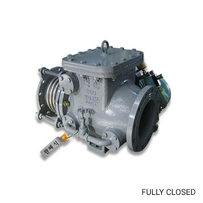
Bellows Check Valves
- Absorbs the expansion and contraction of the tube that occurs when the fluid passes through the free valve inter-face adjustment by the bellows-type expansion device and the expansion and contraction in the axial direction.
- It protects valves and pipeline systems from transitions in all directions (up/down, left/right) caused by ground subsidence and earthquakes and horizontal transitions caused by temperature changes.
- Check valves are used in pipelines for water supply and sewerage systems, and they play a role in protecting the pump or equipment on the pipeline by blocking the reverse flow that occurs when the pump stops operating.
- According to the user's request, it is possible to apply a fully-closing check valve with a dash-pot attached to prevent abrupt closing due to backflow.
- Bypass valve or weight can be applied according to the user's requirement.

- Standard
-
- 200㎜ ~ 1,000㎜ (※ Small diameters of 200㎜ or less and large diameter of 1,000㎜ or more can be manufactured according to customer requirements.)
- Working Pressure
-
- Type 1 : 0.44MPa (4.5㎏/㎠)
- Type 2 : 0.74MPa (7.5㎏/㎠)
- Type 3 : 0.98MPa (10㎏/㎠)
- High pressure of up to 1.57MPa(16㎏/㎠) or higher is possible according to customer's request.
- Valve Joint Part
-
- Flange type, standard specifications are KS D3578, KS B 1511, and other specifications are applicable according to customer's request.
- Working Fluid
-
- Freshwater and seawater
Main part material
| No | Part Name | Material | KS |
|---|---|---|---|
| 1 | Body | Ductile Iron | GCD450 |
| Steel Structure | SS400 | ||
| Stainless Steel Casting | SSC13 | ||
| Steel Casting | SC410 | ||
| 2 | Disc | Ductile Iron | GCD 450 |
| Steel Structure | SS400 | ||
| Stainless Steel Casting | SSC13 | ||
| Steel Casting | SC410 | ||
| 3 | Body seat | Stainless Steel | STS304 |
| Bronze casting | BC6 | ||
| 4 | Disc seat | Bronze casting | BC6 |
| Stainless Steel | STS304 | ||
| Rubber goods for water works | NBR/EPDM | ||
| 5 | Valve seat | Stainless Steel | STS304 |
| 6 | Expansion tube body | Stainless Steel | STS304 |
| 7 | Bellows | Stainless Steel | STS304 |
| 8 | Sleeve | Stainless Steel | STS304 |
External Dimensions
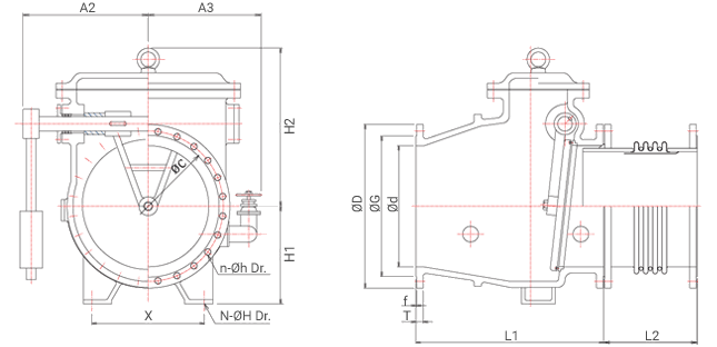
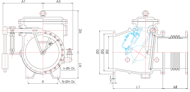
| Nominal Diameter | L1 | L2 | Flange | *A1 (Directly Closed) |
*A2 (Fully Closed) |
*A3 | *H1 | *H2 | ||||
|---|---|---|---|---|---|---|---|---|---|---|---|---|
| ØD | ØC | ØG | n-Øh | T × f | ||||||||
| 200 | 465 | 250 | 342 | 295 | 264 | 8-23 | 22 × 2 | 220 | 400 | 340 | 200 | 390 |
| 250 | 600 | 260 | 410 | 350 | 319 | 12-23 | 24 × 3 | 240 | 460 | 350 | 230 | 450 |
| 300 | 650 | 270 | 464 | 400 | 367 | 12-23 | 24 × 3 | 310 | 520 | 400 | 260 | 490 |
| 350 | 700 | 280 | 530 | 460 | 427 | 16-23 | 26 × 3 | 360 | 580 | 430 | 290 | 530 |
| 400 | 750 | 300 | 582 | 515 | 477 | 16-27 | 26 × 3 | 450 | 620 | 450 | 320 | 600 |
| 500 | 760 | 350 | 706 | 620 | 582 | 20-27 | 28 × 3 | 560 | 690 | 500 | 360 | 680 |
| 600 | 1050 | 400 | 810 | 725 | 682 | 20-30 | 30 × 3 | 650 | 760 | 630 | 430 | 820 |
| 700 | 1200 | 450 | 928 | 840 | 797 | 24-30 | 32 × 3 | 710 | 830 | 690 | 500 | 940 |
| 800 | 1270 | 500 | 1034 | 950 | 904 | 24-33 | 34 × 3 | 760 | 920 | 740 | 560 | 1010 |
| 900 | 1350 | 520 | 1156 | 1050 | 1004 | 28-33 | 36 × 3 | 810 | 970 | 810 | 600 | 1110 |
| 1000 | 1360 | 530 | 1262 | 1160 | 1111 | 28-36 | 38 × 3 | 860 | 1040 | 920 | 650 | 1160 |
1. The flange is KS D 3578 F-12 standard, and other standards can be applied upon request.
2. The valve's face-to-face distance applies to the manufacturer's standard specifications.
3. * The displayed dimensions are for reference only.